
Blog
Keyboard Switch Specifications: How to Read and Compare Them
When choosing keyboard switches, many beginners focus solely on names and prices (such as “Red,” “Brown,” or “Blue” switches). However, these names do not accurately convey the actual tactile experience. Even within the same category, differences in operating force (e.g., 45gf vs. 50gf) or total travel distance (e.g., 3.6mm vs. 4.0mm) can lead to noticeably different user experiences. It is the technical data—the keyboard switch specifications—that truly reveal these nuances.
Keyboard switch specifications serve as a common language between manufacturers and users. This article explores the key technical parameters for both mechanical and magnetic keyboard switches, helping you make more informed choices tailored to your personal preferences.
Why Keyboard Switch Specifications Matter More Than the Name
Switch names are merely simplified classification labels; the actual feel of a switch is determined by its technical specifications. Understanding what these parameters represent helps users avoid the need for blind trial and error. For those involved in procurement or custom keyboard builds, these specifications can be incorporated into technical requirements and acceptance criteria—verified through sample testing—offering a far more reliable approach than relying on product names alone.
How to Read a Force-Travel Curve
A force-travel curve plots travel distance (in mm) on the horizontal axis against force (in gf) on the vertical axis, capturing the switch’s behavior during both the downward press and the upward return. Key metrics—such as actuation force, the peak force of a tactile bump, the reset point, and the bottom-out force—can all be observed on this curve. Interpreting the curve provides a comprehensive understanding of a switch’s operating characteristics.
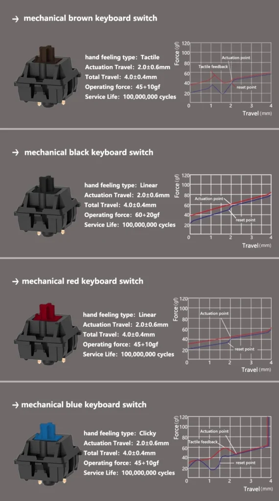
mechanical keyboard switch specification
Take the Unionwell mechanical blue keyboard switch as an example: the curve begins at approximately 30gf, rises to a tactile peak of nearly 60gf at about 1.3mm of travel, drops sharply, and then triggers at roughly 2.0mm. The return curve, meanwhile, illustrates how the force changes as the switch is released.
Actuation Point, Tactile Feedback, and Reset Point
The actuation point indicates the position at which a key-press is registered, determining how far down the key must be pressed. Tactile feedback is generated by the peak in the force curve; the subsequent drop in force provides a distinct physical confirmation that the key has been pressed. The reset point is the position during the upward return where the signal is disconnected, which influences how the switch performs during rapid, consecutive keystrokes.
What the Curve Shape Reveals Beyond the Raw Numbers
The shape of the curve provides information that individual parameters alone cannot convey. A smooth, rising slope corresponds to a linear feel, while a distinct peak indicates a tactile “bump.” The divergence between the downward-press and return curves reflects hysteresis. A curve that grows steeper toward the end may suggest the characteristics of a progressive spring. Consequently, even if two switches share similar nominal specifications, their actual tactile feel can still differ.
Mechanical Keyboard Switch Specifications: The Contact-Based Set
Actuation Force and Bottom-Out Force
Actuation force can be broadly categorized as light, medium, or heavy:
- Switches in the 35–50gf range are considered light, though they may be more prone to accidental presses.
- The 55–68gf range offers a balanced feel—resistant enough to prevent accidental presses while still requiring a deliberate, moderate amount of force.
- Switches requiring over 70gf demand significant force, which can lead to fatigue during extended typing sessions.
Furthermore, when comparing actuation forces, it is essential to verify how they are measured. Since different manufacturers may use varying measurement methodologies, identical “gf” (gram-force) values do not necessarily guarantee an identical feel. Additionally, actuation force and bottom-out force should be considered separately. Users with a “light touch” tend to focus on actuation force, whereas those who habitually bottom out their keys should pay closer attention to the bottom-out force and the delta between it and the actuation force.
Pre-Travel, Total Travel, and the Reset Gap
Pre-travel refers to the distance a switch travels from its resting position to the actuation point; a shorter pre-travel results in faster actuation. Total travel defines the full distance the switch moves before bottoming out, while the distance between the reset point and the actuation point influences the experience of releasing and re-pressing a key during rapid, consecutive keystrokes.
Tactile Peak, Click Mechanism, and Spring Options
The intensity of the tactile feedback in a “tactile” switch is determined by the tactile peak and the shape of the force curve. The “click” sound is produced by a dedicated mechanism and is not solely determined by the actuation force. While common mechanical keyboard switch springs typically range from 14mm to 22mm in length, this dimension alone does not dictate the feel; factors such as wire gauge, number of coils, and spring stiffness are equally significant.
Electrical Life vs. Mechanical Life
Mechanical life refers to the total number of physical actuations a switch can endure, whereas electrical life refers to the number of cycles it can perform while maintaining reliable electrical contact. These two metrics should not be conflated; low-level electrical signals in keyboard switches can be affected by factors such as contact oxidation. While appropriate contact materials and surface treatments can enhance signal reliability, they do not serve as a direct indicator of a switch’s mechanical lifespan.
Magnetic Keyboard Switch Specifications: The Flux-Based Set
Magnetic keyboard switches utilize a magnet within the stem and a Hall-effect sensor on the PCB to detect positional changes, enabling signal actuation without the need for physical mechanical contacts. Consequently, in addition to standard mechanical switch parameters, one must also consider magnetic flux readings, actuation settings, and environmental (temperature) effects.
Initial Flux and Bottom-Out Flux
“Initial flux” refers to the magnetic induction reading when the switch is in its released (resting) state, while “bottom-out flux” corresponds to the reading when the switch is fully pressed. The range between these two values helps define the sensor’s detection window, though it should not be equated directly to the adjustable actuation travel. Factors such as PCB thickness, magnet positioning, and sensor architecture all influence these readings; therefore, when comparing magnetic flux specifications, it is essential to verify that the measurement conditions are consistent.

magnetic keyboard switch
Custom Actuation Travel and RT Precision
In traditional mechanical switches, the actuation point is typically fixed by the internal physical structure. In contrast, magnetic switches allow for software-defined actuation thresholds, with the specific range determined by the switch design and the keyboard system. “Rapid Trigger” (RT) functionality enables dynamic actuation and reset based on the direction of key movement and user-defined thresholds—an ideal feature for scenarios requiring rapid, repetitive inputs.
Spring Length and the Upstroke Feel
Magnetic switches often incorporate extended springs (e.g., 21mm or 23mm) to achieve specific rebound characteristics. However, the actual rebound speed depends on a combination of factors, including spring stiffness, pre-compression, internal friction, and the overall structural design. The bottom-out force is also a key metric; for instance, a specified bottom-out force of ≤ 85gf ensures that the pressure required to fully depress the key remains within a controlled range.
Lifespan and Environmental Parameters Without Contacts
Unionwell’s magnetic keyboard switches are rated for a lifespan exceeding 100 million actuations. While the absence of physical mechanical contacts eliminates contact wear, other components—such as the stem, spring, and various moving parts—may still experience wear over time, which can affect long-term reliability. Furthermore, operating temperature and humidity are critical, as they can influence magnetic output and sensor readings. It is therefore important to ensure that the product’s specified environmental operating range aligns with the actual conditions of use.
Specification Comparison Table: Mechanical Keyboard Switches vs. Magnetic Keyboard Switches
|
Parameter |
Mechanical Keyboard Switch |
Magnetic Keyboard Switch |
Selection Focus & Key Insights |
|
Signal Source |
Physical make-and-break via metal contacts; instant conduction with snap-action structure. |
Hall element senses magnet position; no physical contact points. |
Determines the lifespan model and signal consistency mechanism. |
|
Operating Force (OF) |
Commonly 35–70 gf; fixed at factory and non-adjustable. |
Typically 35±5 gf; total travel pressure <85 gf. |
Light-touch users focus on Operating Force; bottom-out users focus on Bottom-out Force. |
|
Actuation Travel |
Fixed at factory (e.g., actuates at 2.0 mm out of 4.0 mm total travel). |
Customizable / Adjustable. |
Shorter actuation suits competitive gaming; longer actuation avoids accidental keypresses during typing. |
|
Total Travel |
Typically 3.3–4.0 mm. |
Typically 3.20±0.10 mm. |
Longer travel provides a fuller bottom-out feel; shorter travel requires less effort. |
|
Spring Length |
Commonly 14–22 mm. |
Extended springs, e.g., 21 mm or 23 mm. |
Longer springs offer a more lively and responsive rebound. |
|
Force Curve Profile |
Three main types: Smooth Linear, Tactile bump, or Clicky sound. |
Primarily Linear; the force curve is dictated by magnet travel. |
Tactile sensation comes from physical bumps, not just raw force magnitude. |
|
Lifespan Rating |
Mechanical lifespan and Electrical lifespan are rated separately. |
No contact wear; lifespan >100 million cycles. |
High-load circuits must be evaluated based on electrical lifespan. |
FAQ
Q1: Why do specifications show ±5gf instead of a single, exact number?
A1: Keyboard switches inherently have tolerances—arising from variations in spring wire diameter and the number of coils, differences in assembly height, and positioning variances within measurement fixtures. This ±5gf notation is both a sign of transparency and an indicator of quality control standards.
Q2: Does a longer spring always result in a heavier switch?
A2: Not necessarily. A spring’s stiffness is determined by a combination of its wire diameter, number of coils, and effective length; length is just one of these variables. Under the same preload, a longer spring often provides a lower initial force, yet offers more uniform rebound and a more responsive upward stroke. Conversely, a shorter spring can create a snappier, more “propulsive” feel.
Q3: Why does magnetic flux depend on PCB thickness?
A3: Hall-effect sensors are soldered onto the PCB, while the magnet is housed within the switch stem; the distance between them is determined by both the PCB thickness and the switch’s internal structure. Using a 1.6mm PCB versus a 1.2mm PCB will result in different magnetic flux readings for the same switch, which in turn shifts the range for setting actuation thresholds.
Q4: Is a higher bottom-out force necessarily a bad thing?
A4: Not necessarily—it depends on your typing style. For users with a light touch who rarely bottom out, this parameter is largely irrelevant. For those who frequently bottom out, however, the impact felt at the end of each keystroke is determined by the bottom-out force. For the latter group, a switch with a smaller difference between its operating force and bottom-out force can actually be less fatiguing.
Q5: What does “RT 0.001” actually mean in daily use?
A5: “RT” stands for Rapid Trigger, while “0.001” refers to the resolution level for magnetic flux or positional detection. In practical terms, this means two things: actuation points can be set with extreme precision, and the thresholds for triggering (pressing down) and resetting (releasing) occur almost instantaneously.
Conclusion
Keyboard switch specifications make it easier to quantify both feel and performance. The core specifications for mechanical switches center on contact mechanisms and force-travel curves, encompassing operating force, travel distance, tactile peak, and electrical lifespan. For magnetic switches, additional factors must be considered, such as magnetic flux, adjustable actuation points, Rapid Trigger (RT) settings, and environmental influences.
When reviewing specification sheets from keyboard switch manufacturers, one should examine the force-travel curve, parameter tolerances, and testing conditions. The curve illustrates actuation characteristics, tolerances reflect manufacturing consistency, and testing conditions determine whether data points are truly comparable. Evaluating these three elements together allows for a more reliable assessment of whether a given switch is suitable for a user.